2014.04.30 Fotodokumentasjon, referansepunkter, arkivering og lagring.
Dette var dagen for foto dokumentasjonen av hva som befant seg hvor innvendig i nese og cockpitseksjonen. Det er viktig at vi har sikret oss et solid fotomateriale av hvordan ting har sett ut, før demonteringen begynner. Vi fotograferer områdene fra spant til spant, fra bunnen til topp, og gjerne ned igjen, for å sikre oss at alle detaljer blir avbildet. For å sikre identifisering av hvor bildene er tatt, brukes Heinkel fabrikkens eget nummersystem for de forskjellige spantene. I dette systemet benevnes spantene, fra front av neseseksjonen og bak til skottet mot cockpit, med de romerske tallene I til V. Fra fremre skott, i cockpitseksjonen og bak til skottet mot senterseksjonen, brukes de arabiske tallene 1 til 6.
-

-
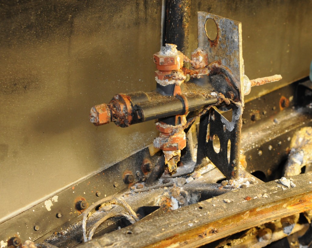
Bombesikterens hydrauliske åpne og lukkeventil for bombeluker
. Ventilen er plassert på styrbord siden ved spant II.
Alle deler skal før demontering i tillegg bli grundig fotografert slik at en senere kan finne tilbake til hvor de har vært plassert, og til hvordan de har vært montert. Plassering blir referert til hvilken side og hvilke(t) spant utstyret har vært montert på. Delene blir merket med unike tag nummer, før de registreres i et papir skjema.
-

-
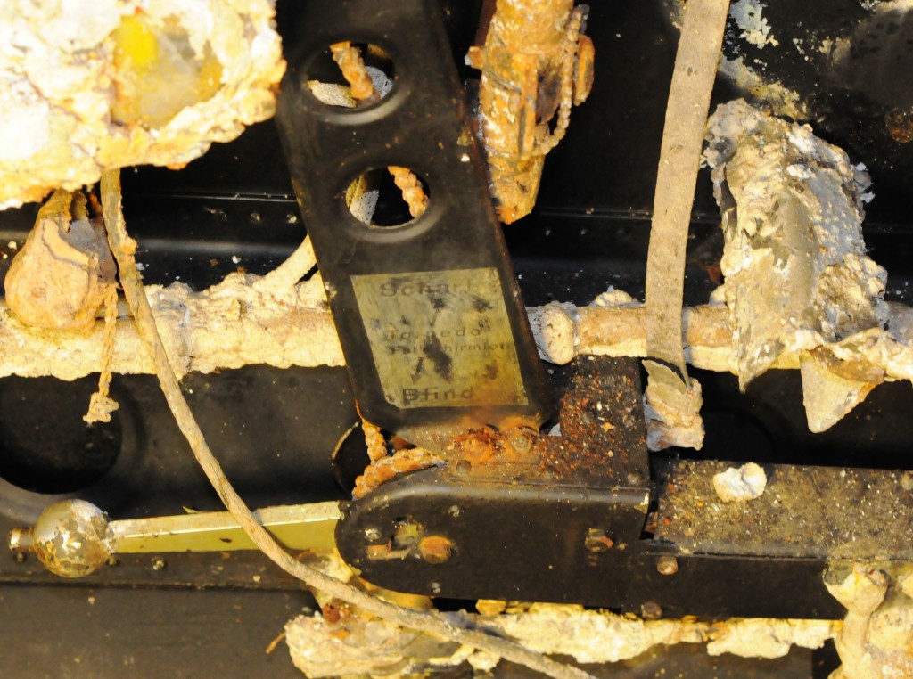
Hendelen er plassert på styrbord side , mellom spantene IV- V, og ble brukt til å løse ut torpedoen
De blir så på ny grundig fotografert for å dokumentere både tilstand, og hvordan delen er bygget. Bildene blir så registrert i det samme papir skjemaet, og siden lagret med sporbarhet mot tag, spant og dato for demontering. Det hele blir så registrert i et Excel skjema for å sikre en overordnet sporbarhet i det hele.
-
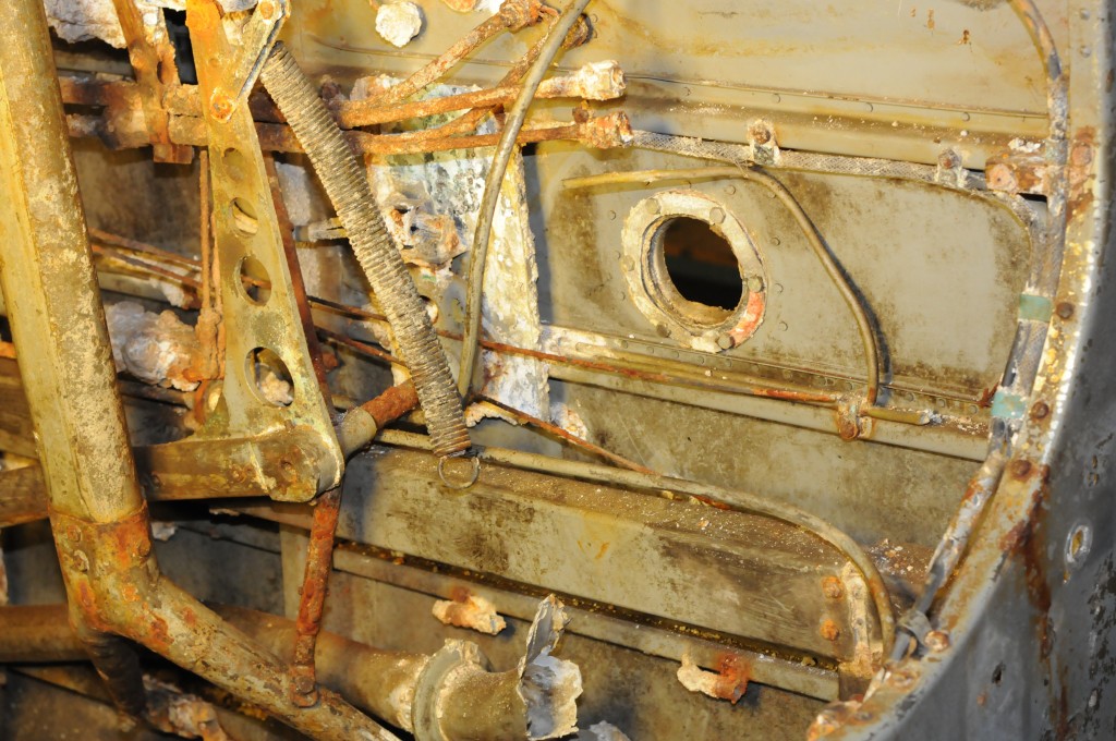
. bakre del av mekanikken for starting av nødutpumping av drivstoff, nedre del av setestøtte og gjennomgang for varmluftsrør fra eksosmanifoil.” width=”640″ height=”425″ />
Styrbord side mellom spantene 5- 6. En ser her bl.a. bakre del av mekanikken for starting av nødutpumping av drivstoff, nedre del av setestøtte og gjennomgang for varmluftsrør fra eksosmanifoil.
Deler som tas ut blir lagret i et mindre vannkar i påvente av en grundig vurdering og konservering. Noen deler blir satt grundig inn med Lanolin og lagret tørt.


