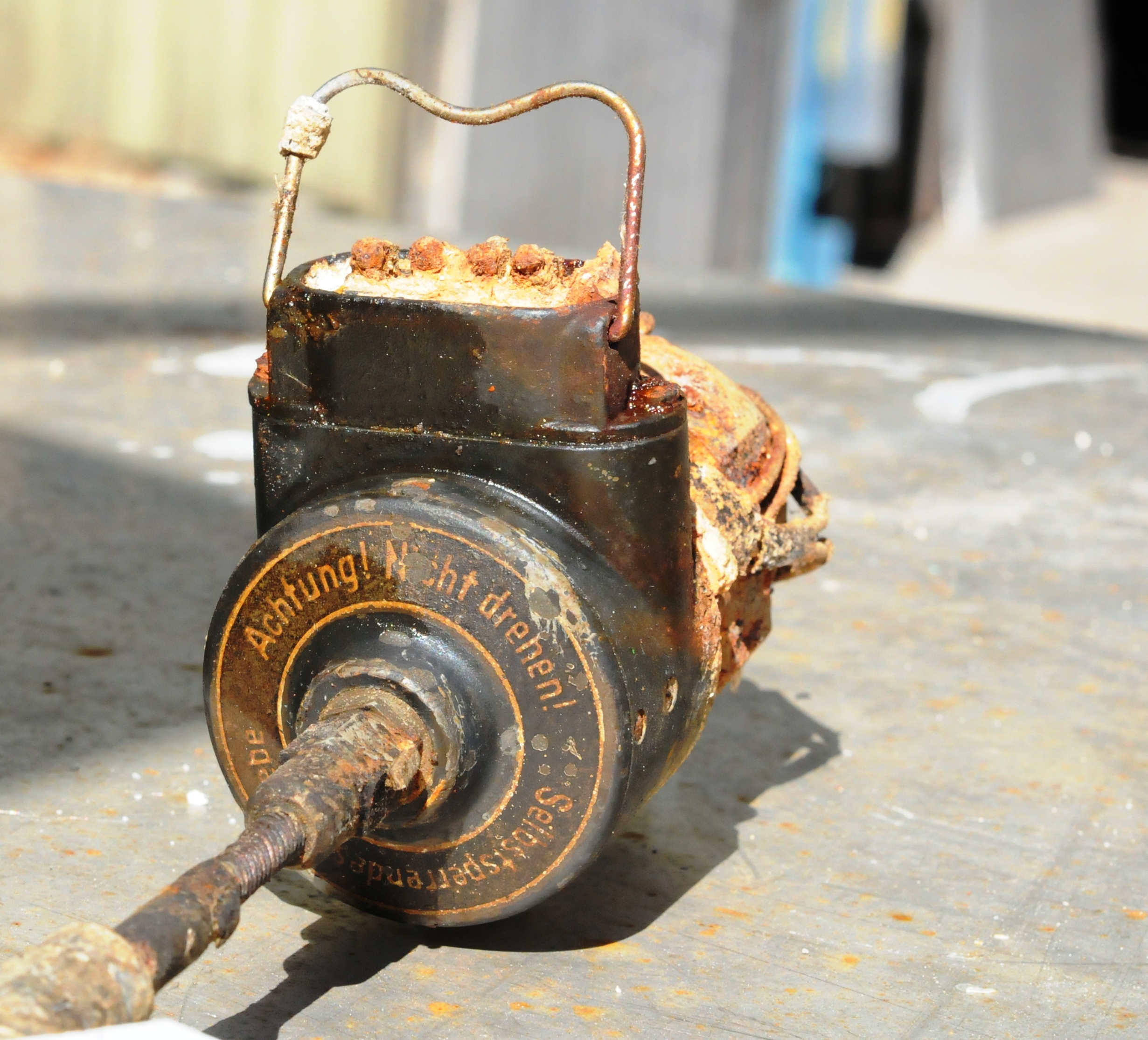
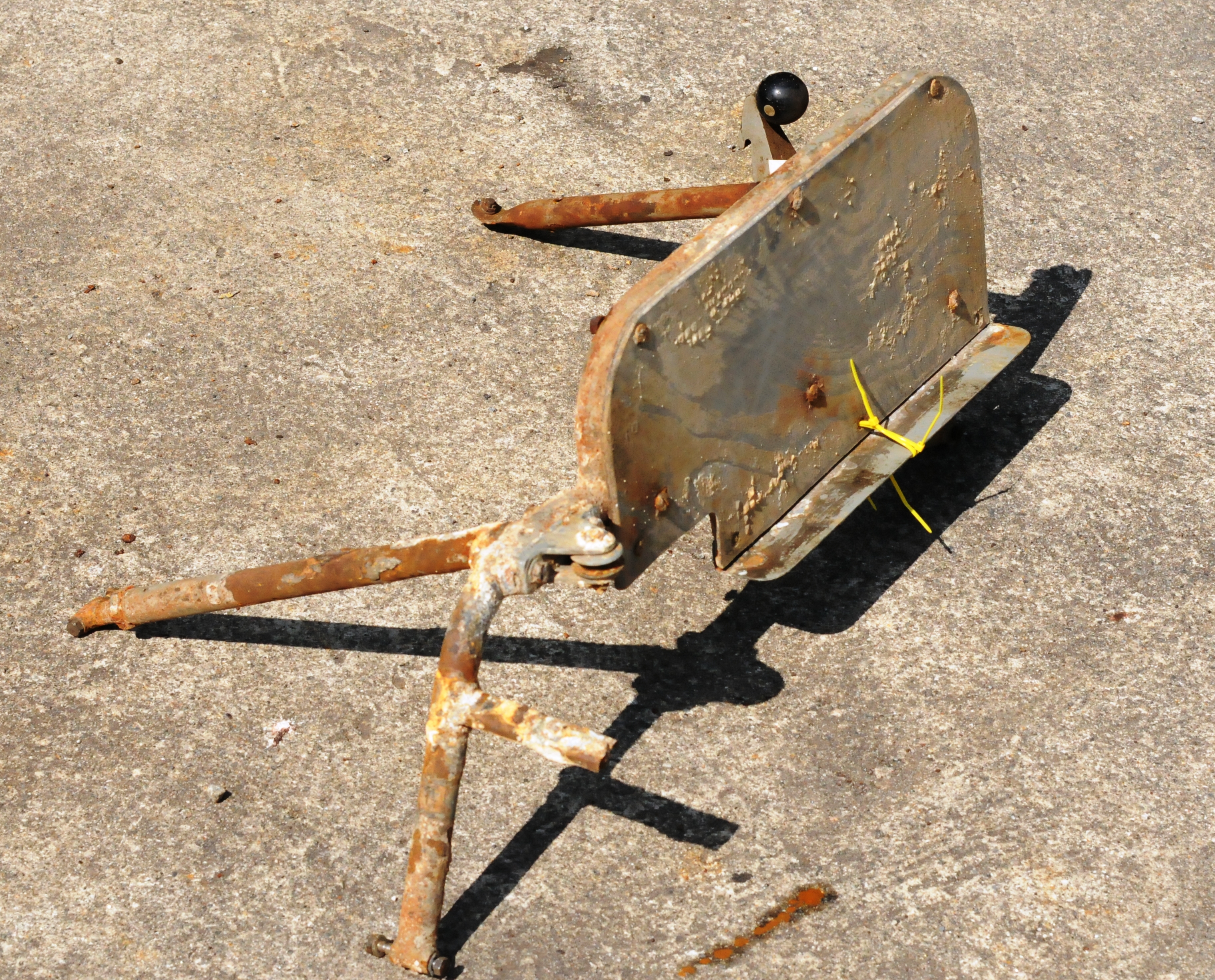
Flyet har hatt et system for i nødsituasjoner å kunne dumpe drivstoff. Vi demonterte i dag den manuelle delen av systemet
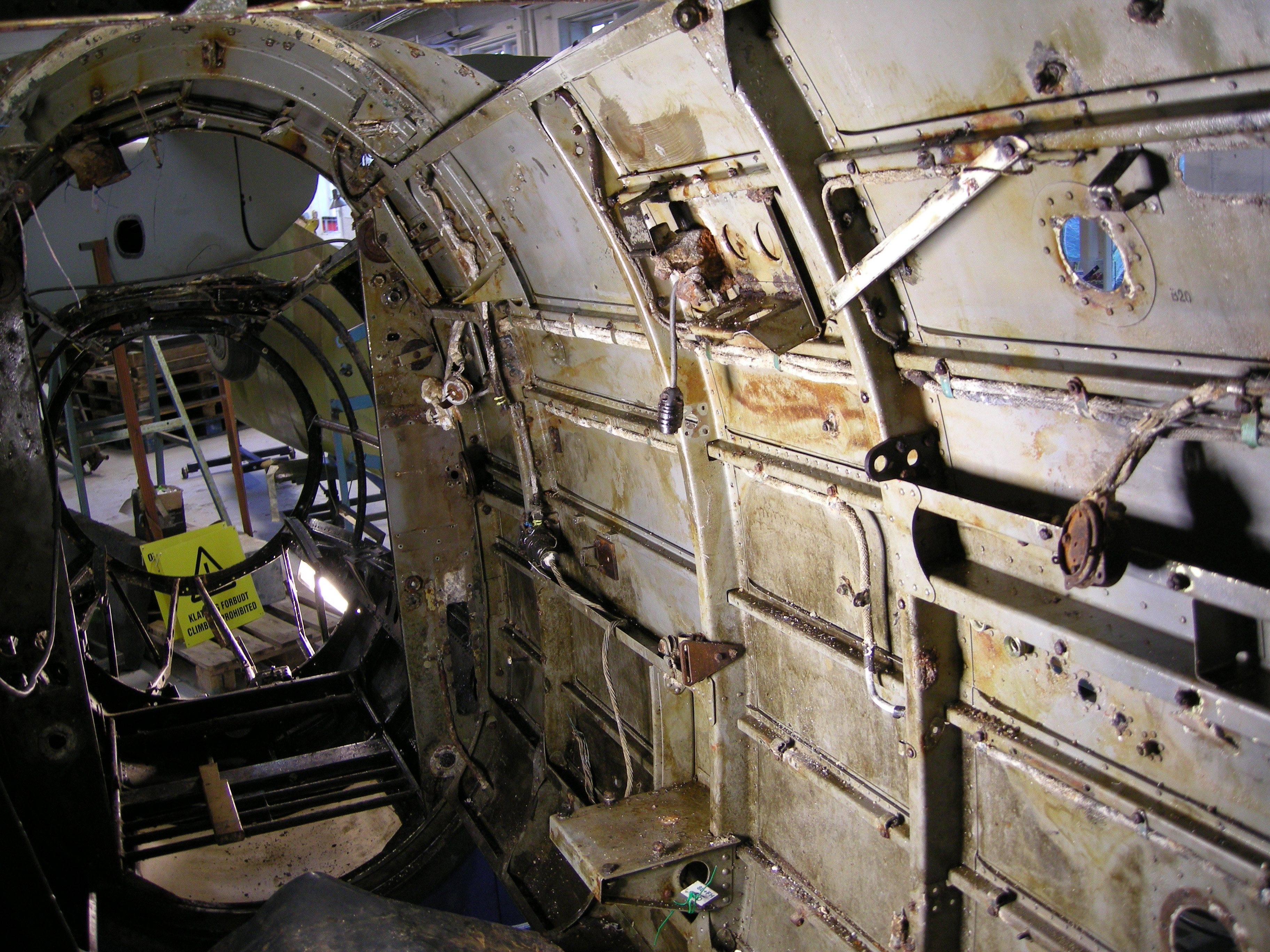
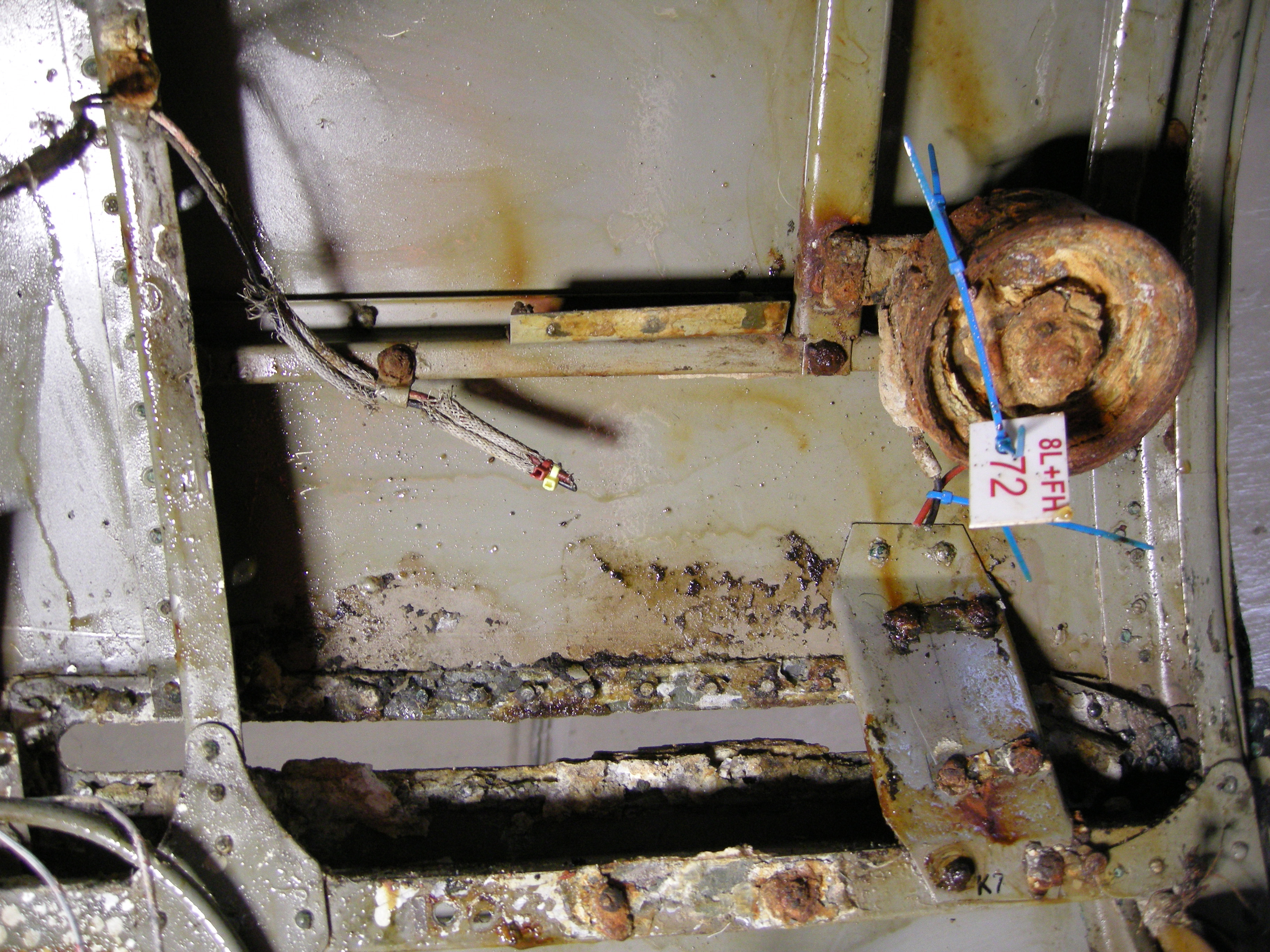
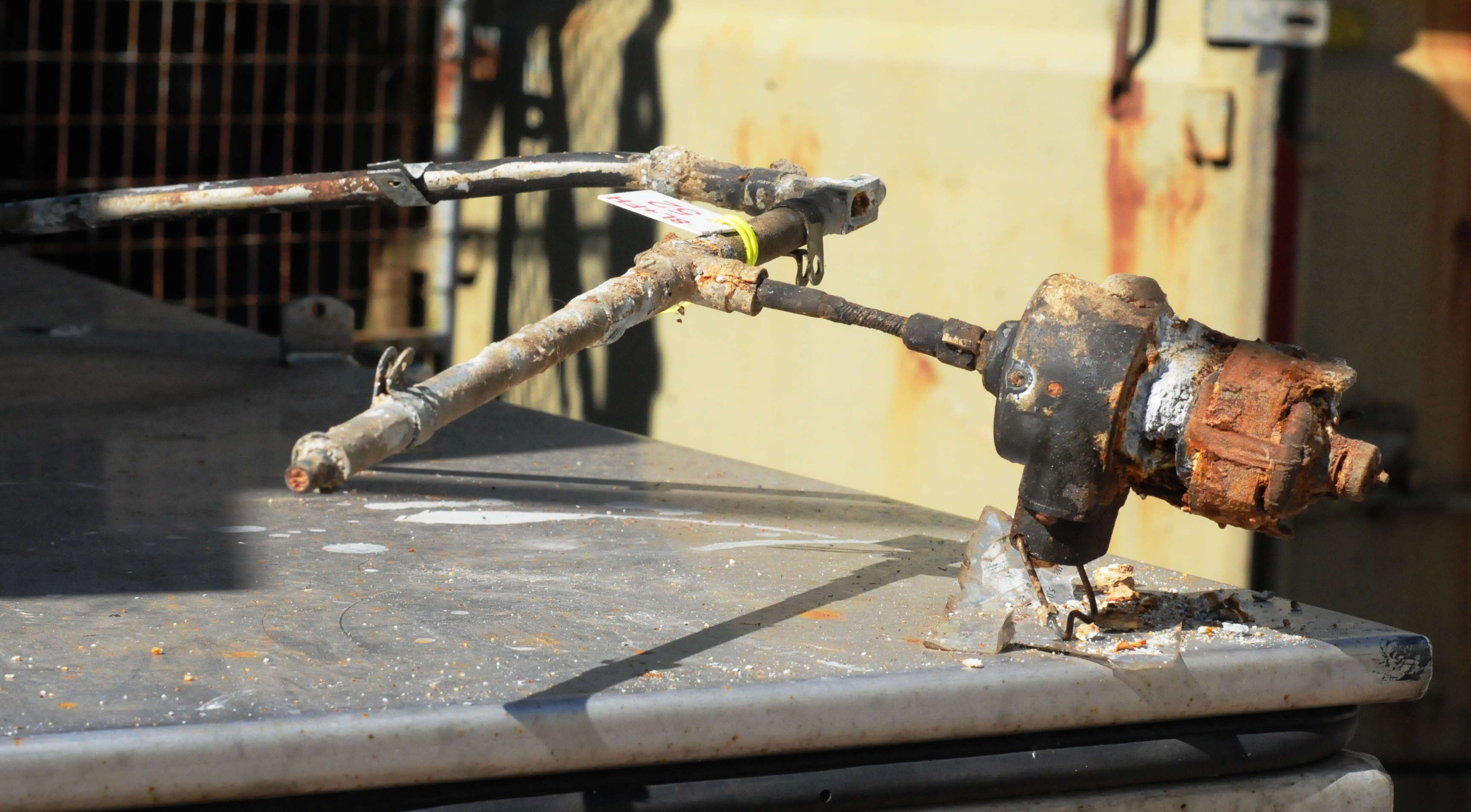
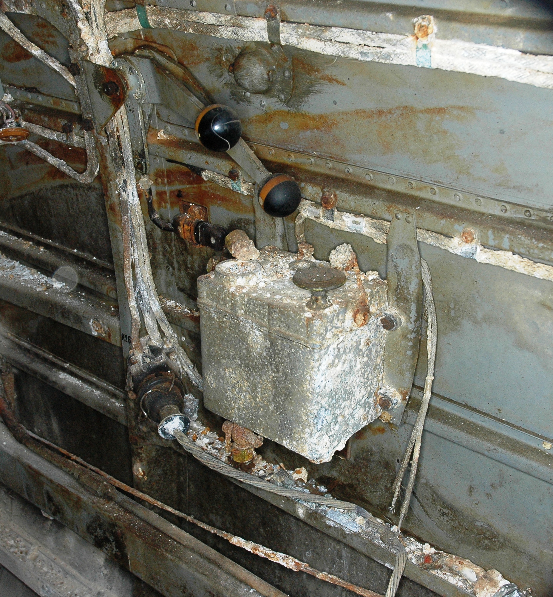
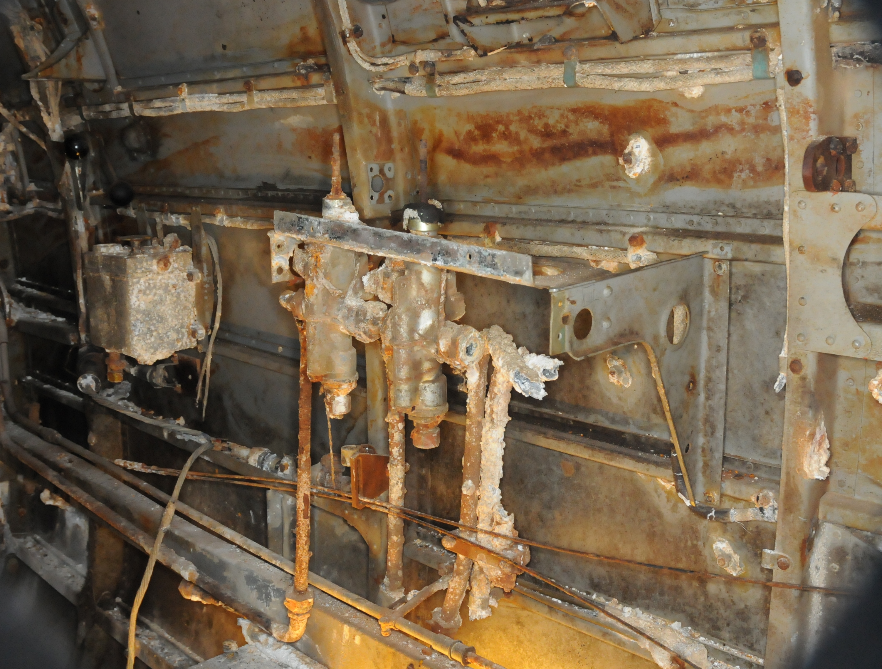
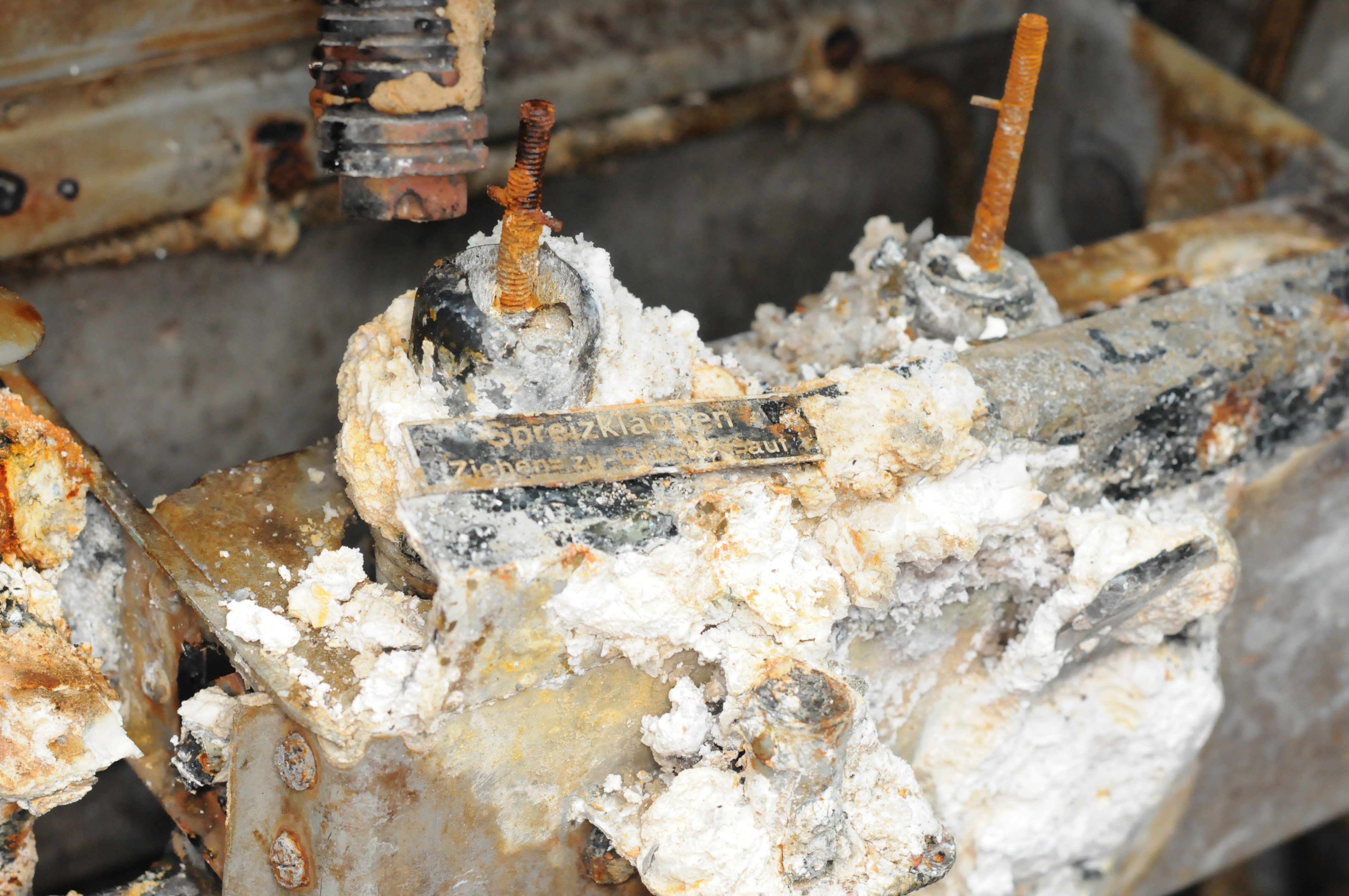
. En lang vertikal hendel var festet til samme brakett, som manøverventilene for hydraulisk flaps kontroll, plassert på styrbord side mellom spantene 3a- 4. Denne ga piloten mulighet til å starte en utpumping av brennstoff. Hendelen var del av et større manuelt arrangement, som endte opp bak mellom spantene 5- 6. Her var dette koblet mot en plate, hvor posisjonen ble overvåket av en grensebryter
. Fra denne er det rutet ledninger bakover i retning til en elektrisk pumpe for utpumping av drivstoff.
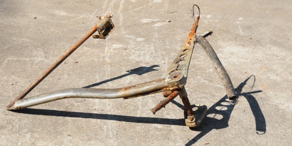
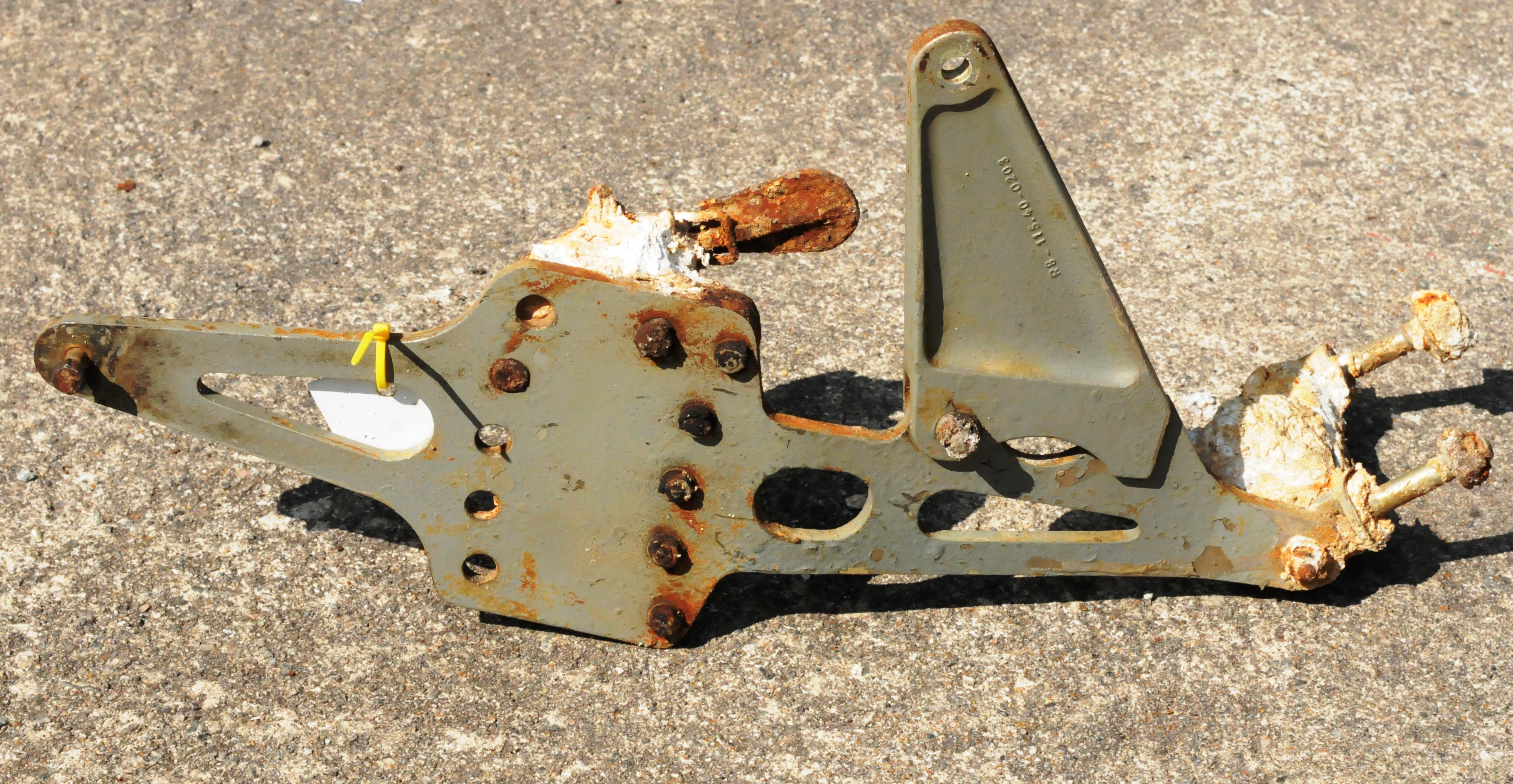
- Utstyr for betjening av system for nød dumping av drivstoff
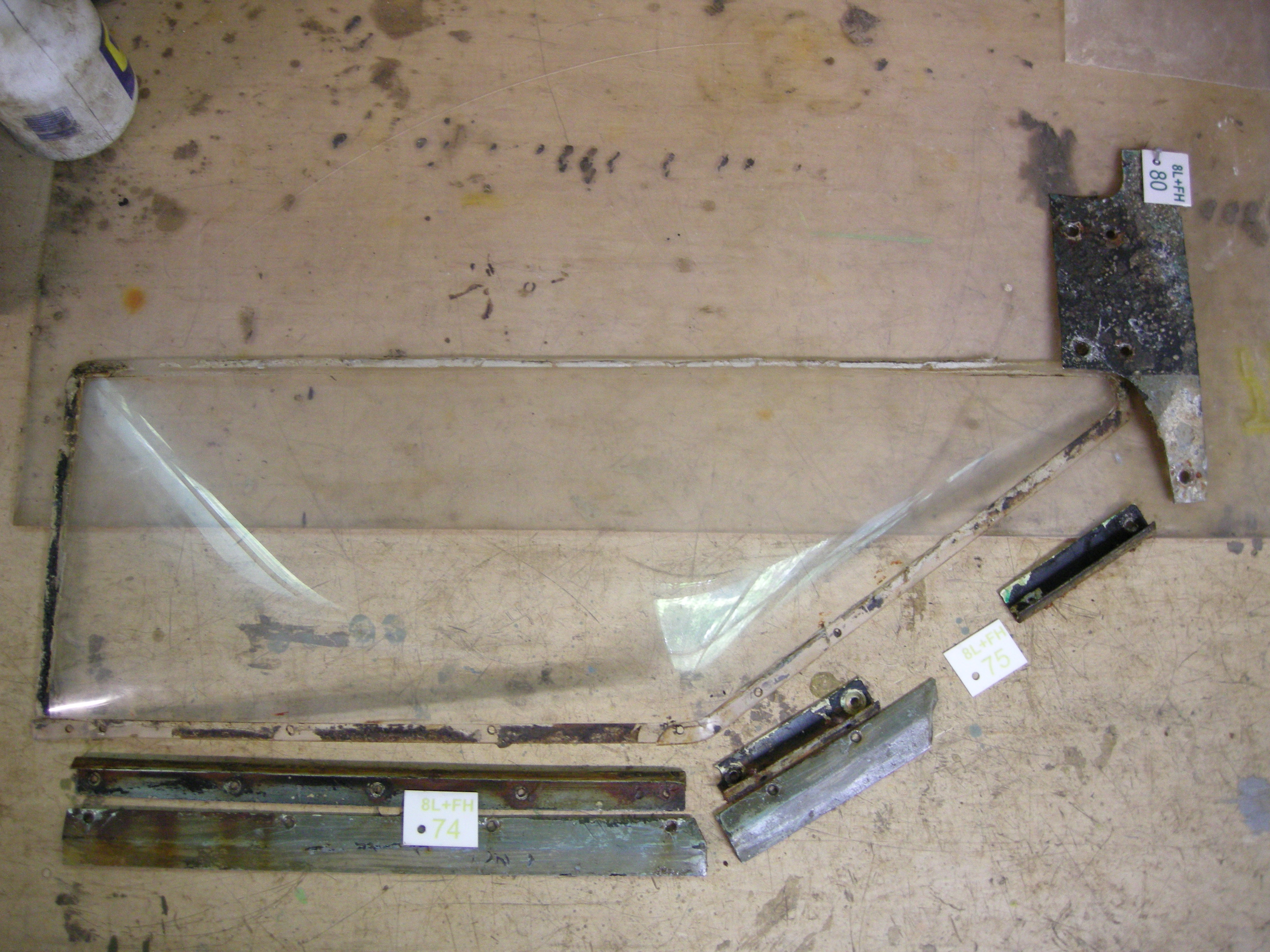
Et lukkevindu på toppen rett bak spant I ble løsnet og tatt ut.
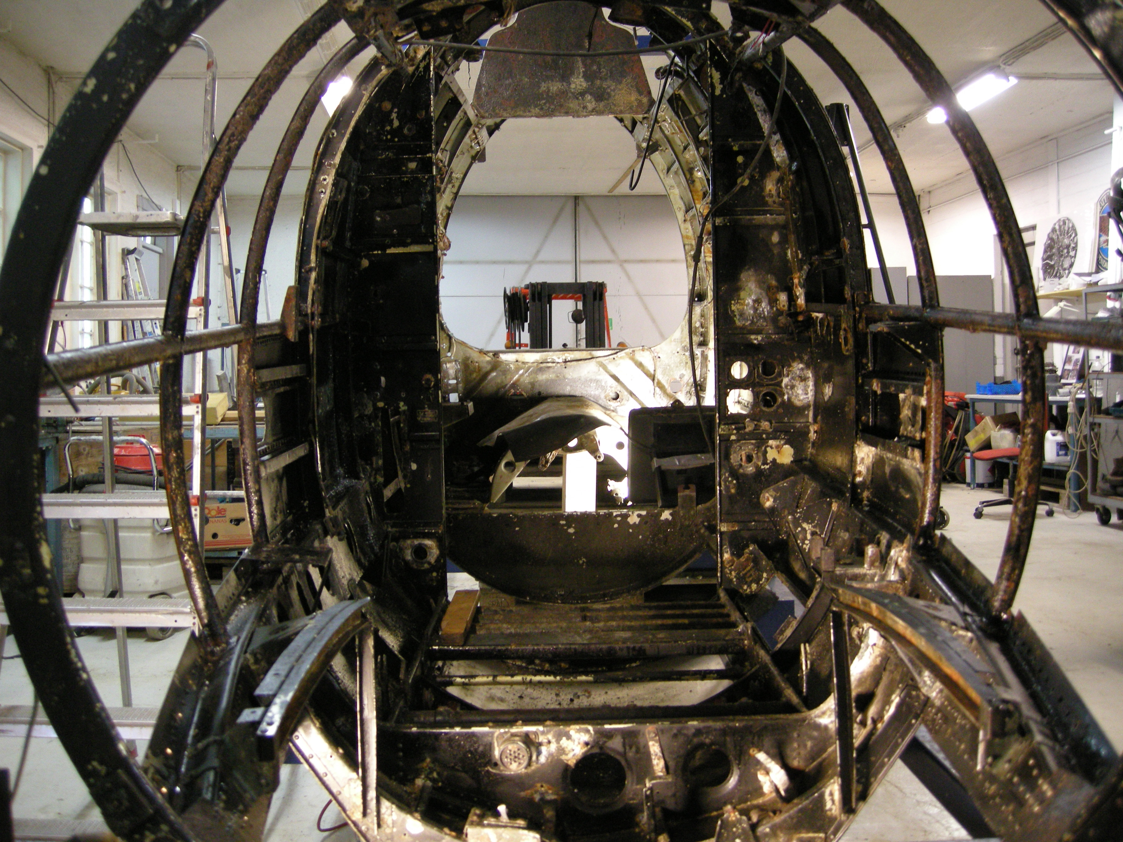
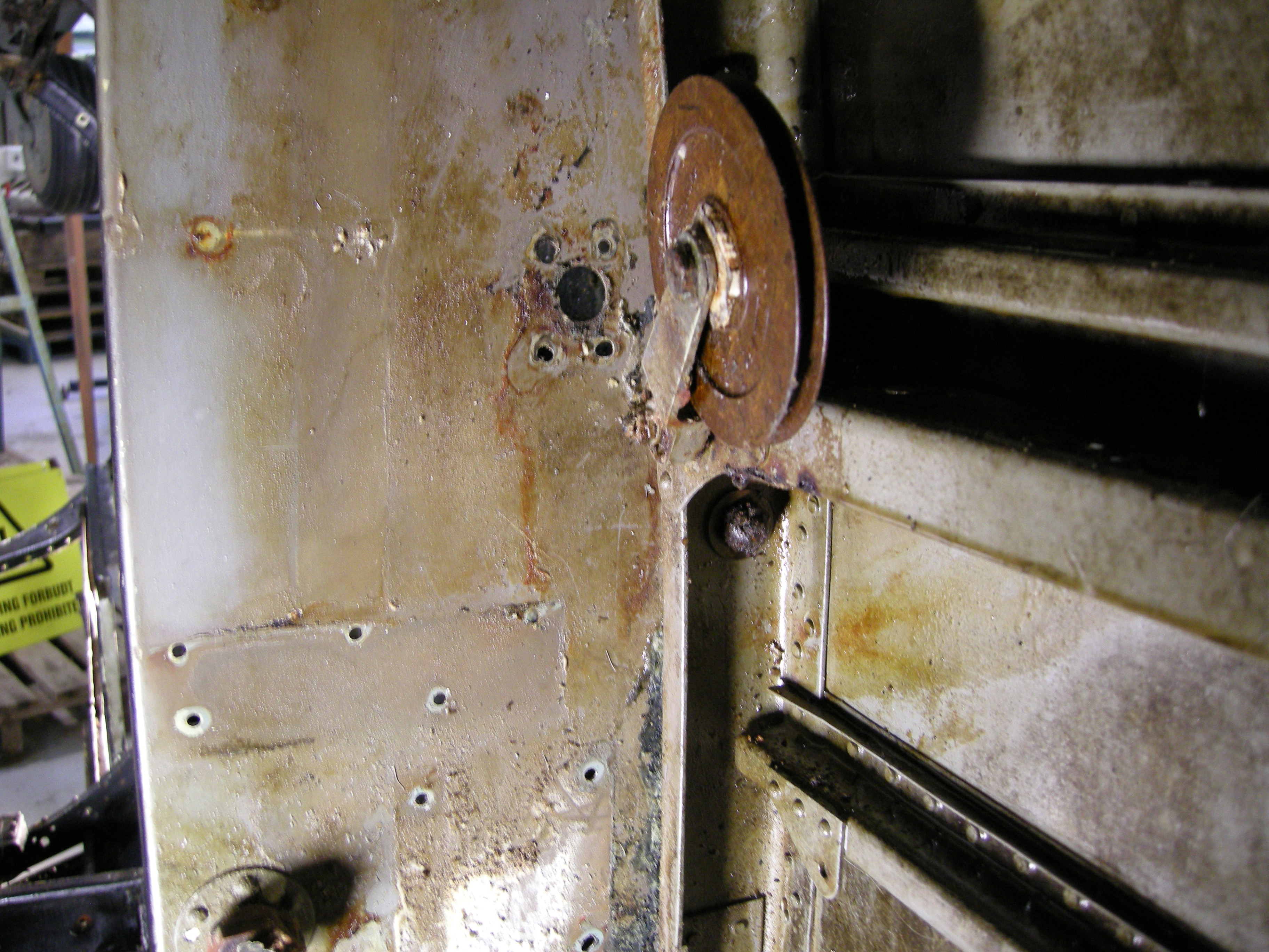
Pilotens styrbord stigbrett, med tilhørende brakett og en trinse, ble demontert fra området mellom spant 2- 3a. Det ble også funnet en rørdel liggende bak stigbrettet. En treplate som har tilhørt stigbrettet ble også tatt ut.

- Stigbrett for piloten
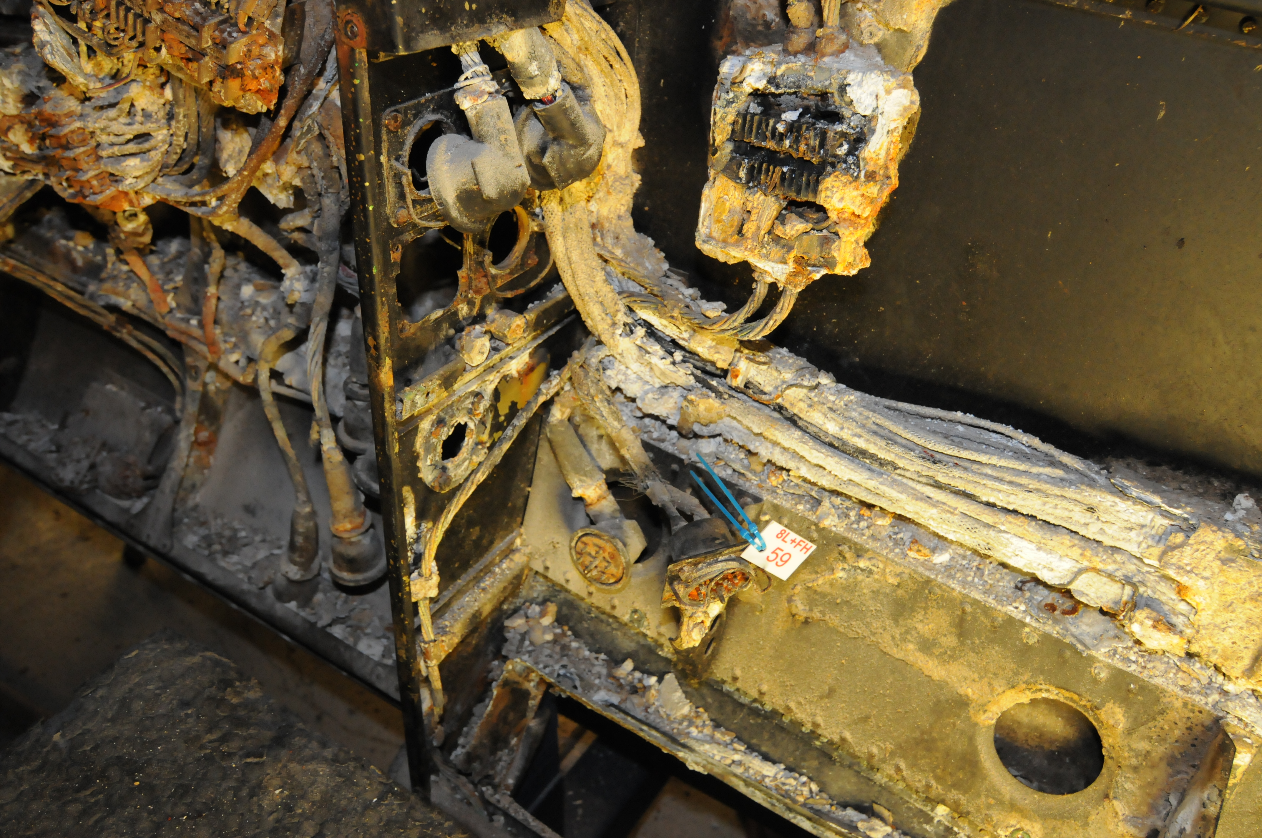
Vi tok også ut flere mindre deler fra flyet:
-
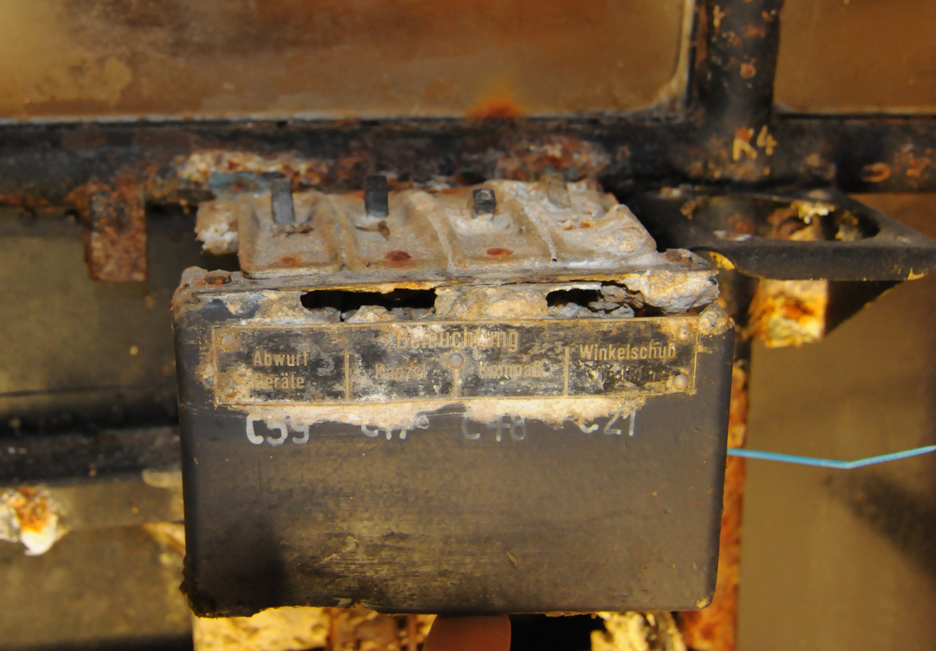
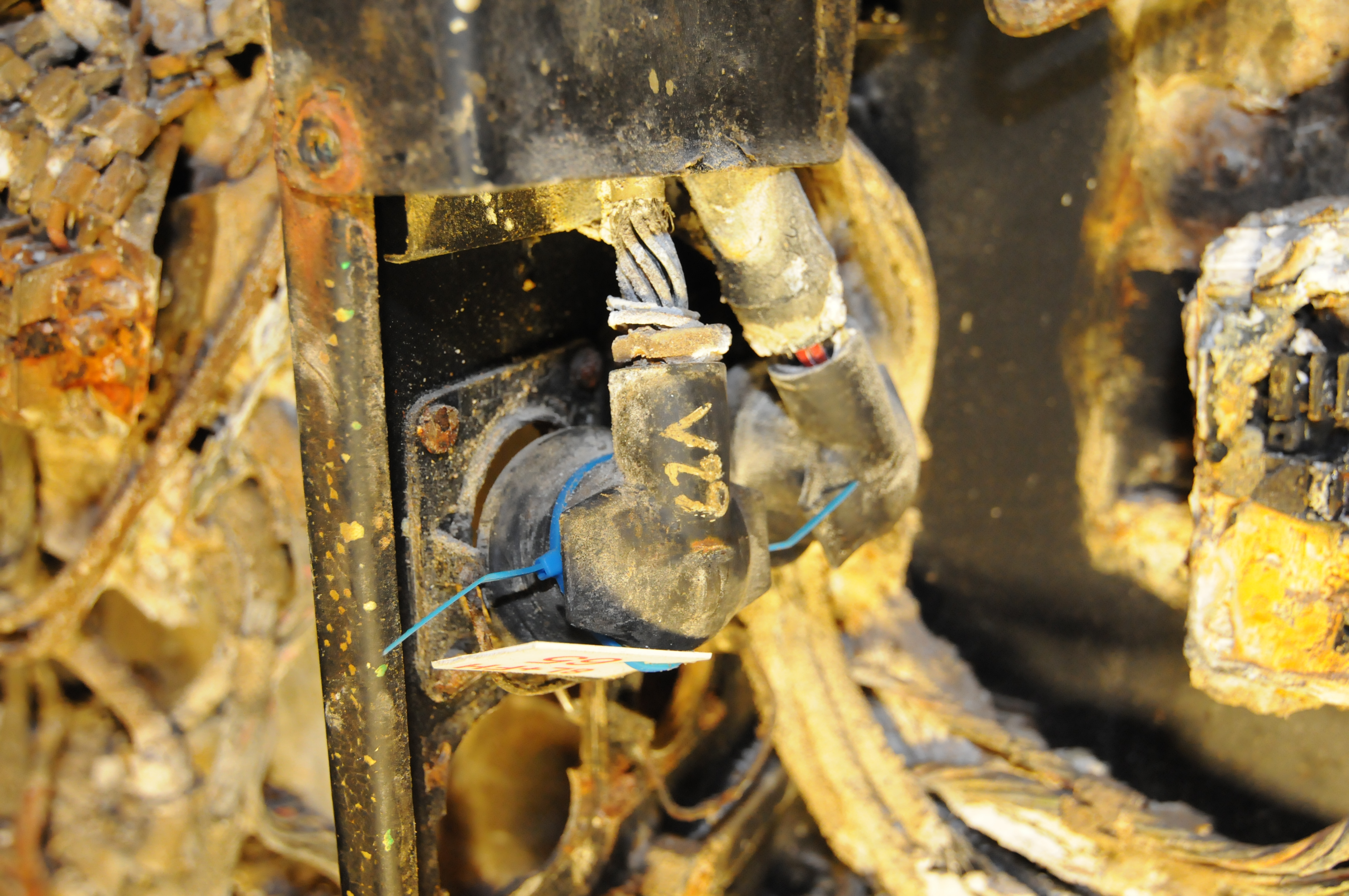
En stikkontakt som har vært koblet mot hovedledningsgaten nede på babord side ved spant II.
-
Et løst stag som lå oppå pilotens stigbrett på styrbord side mellom spantene 2- 4.
-
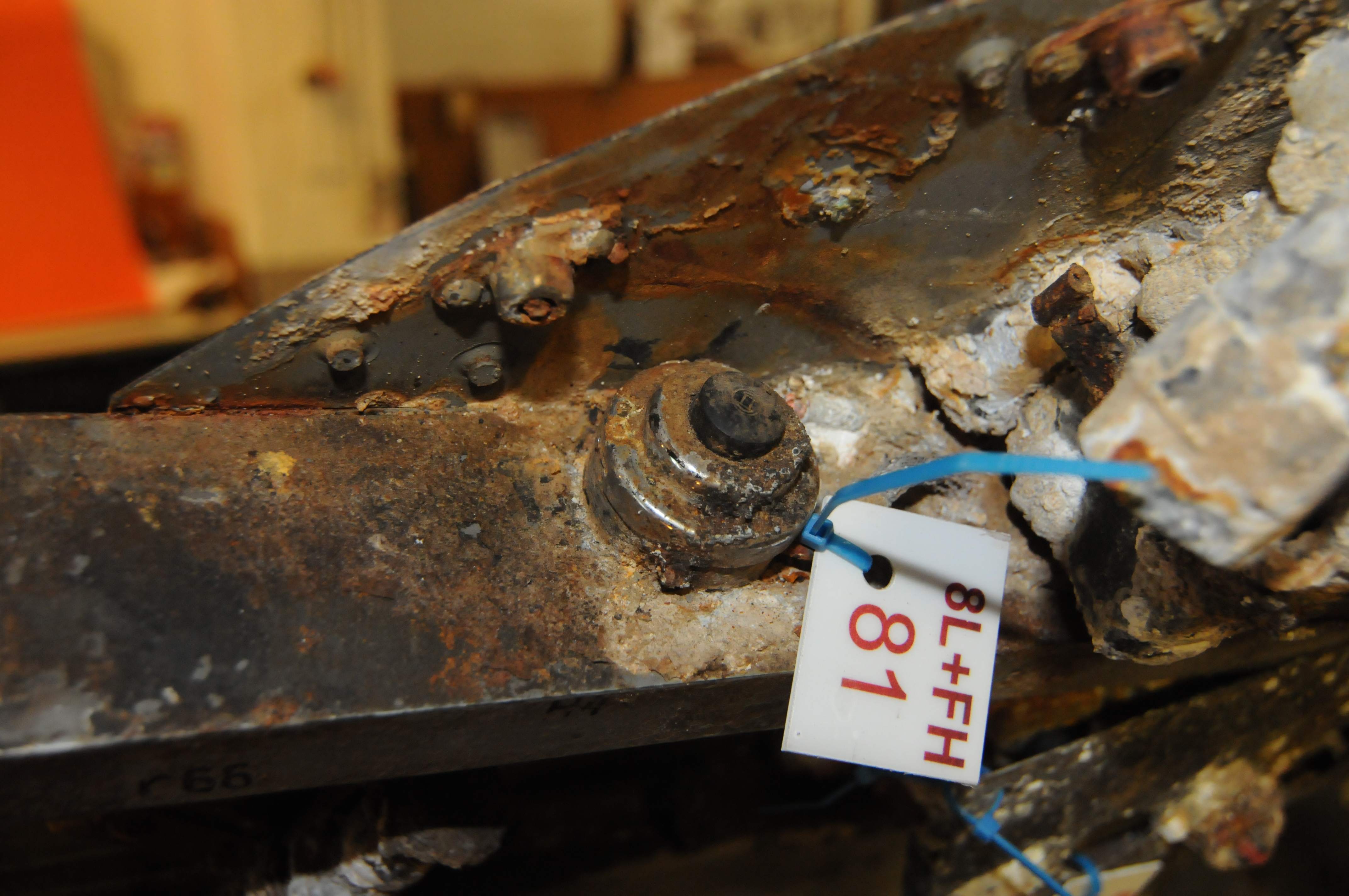
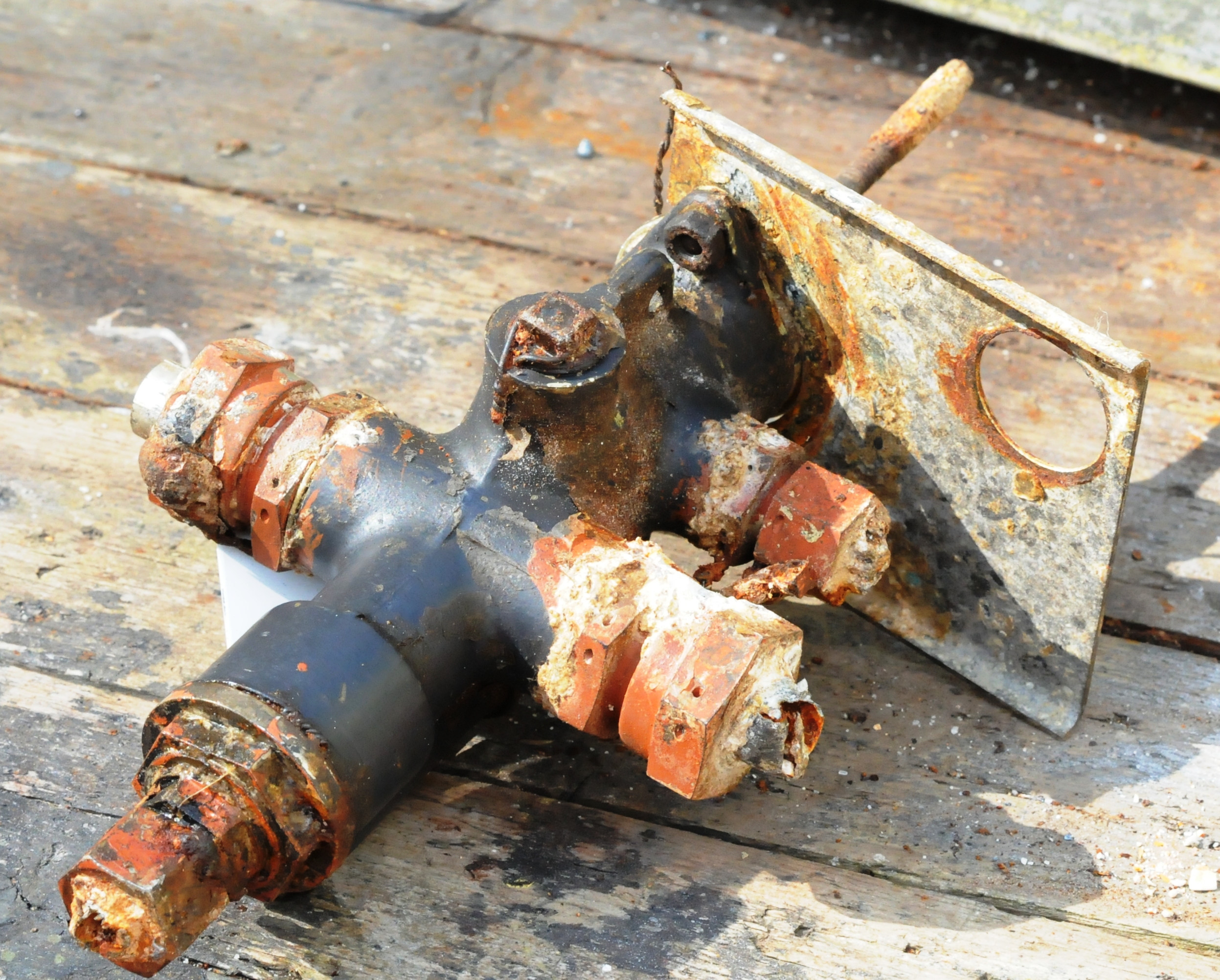
En innretning med ukjent funksjon som trolig har vært en ventil med håndtak, ble funnet nede på styrbord side mellom spantene 5- 6.
-
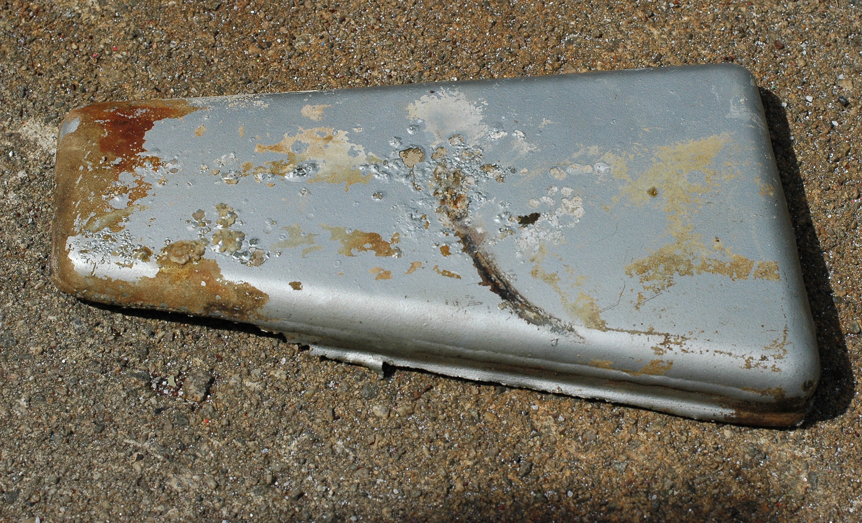
En rørdel som har tilhørt varmluftsystemet, og som stakk opp og ut fra rommet bak den store sikringsboksen ved pilotens babord fotbrett, mellom spantene 2- 3.
-
Flere T- koblinger som har tilhørt hydraulikksystemet, og har vært plassert et sted mellom spantene 1- 6, ble funnet liggende på dørken.