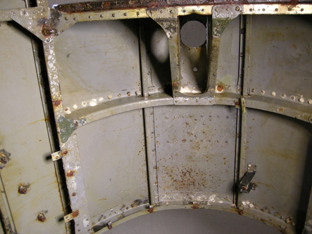
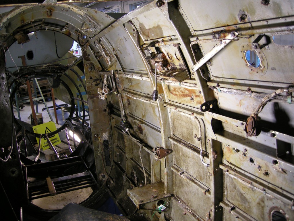
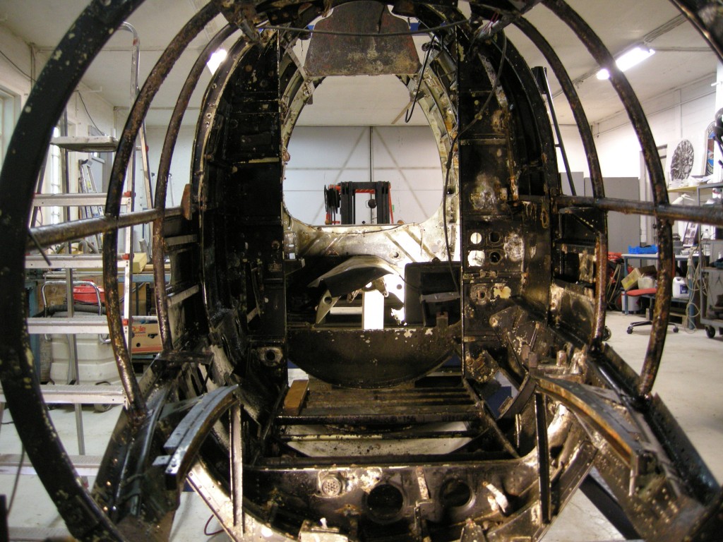
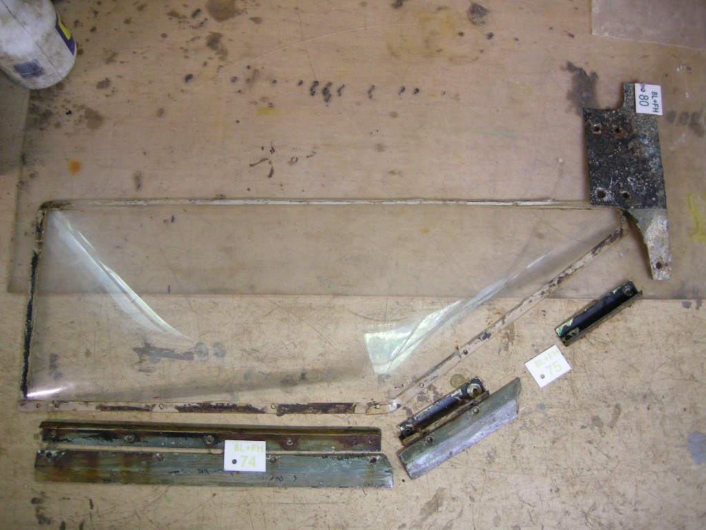
We now have so much experience with turning out windows, that we this day got loose most of the remaining plexiglass windows on the port side:
-
Window – lower – foremost- spun In- II.
-
Window – On top – foremost- spun In- II.
-
Window – top center- spun In- III.
-
Window – lower – rear- spun In- III.
-
Window – On top – rear- spant III- IV.
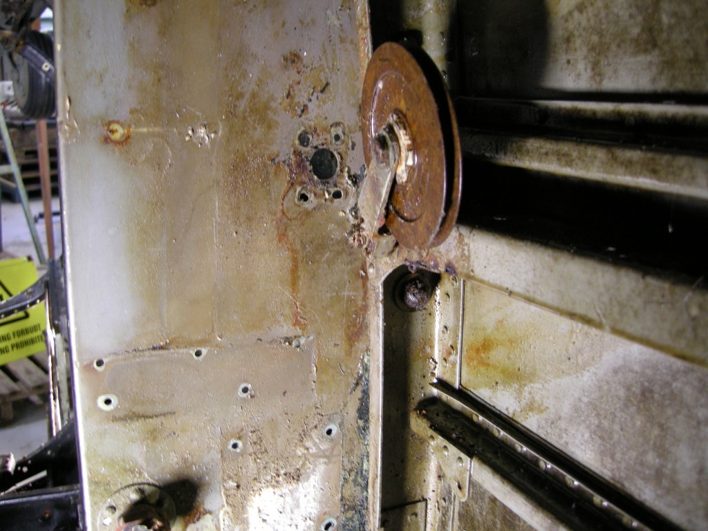
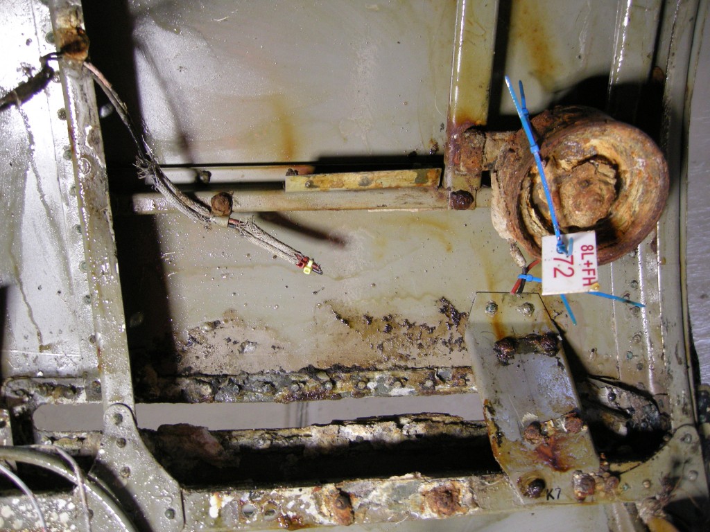
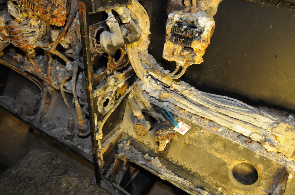
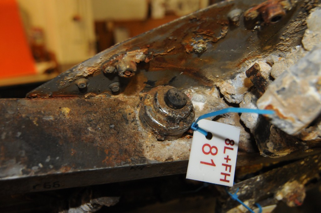
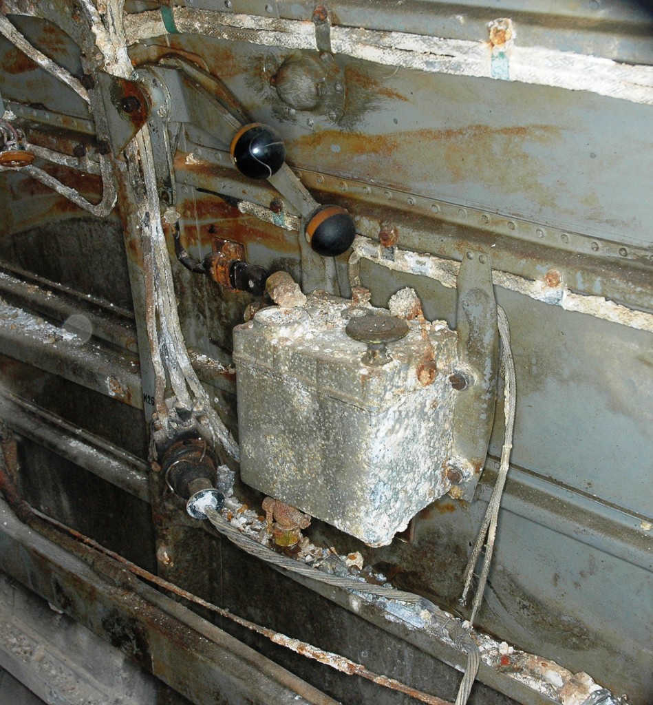
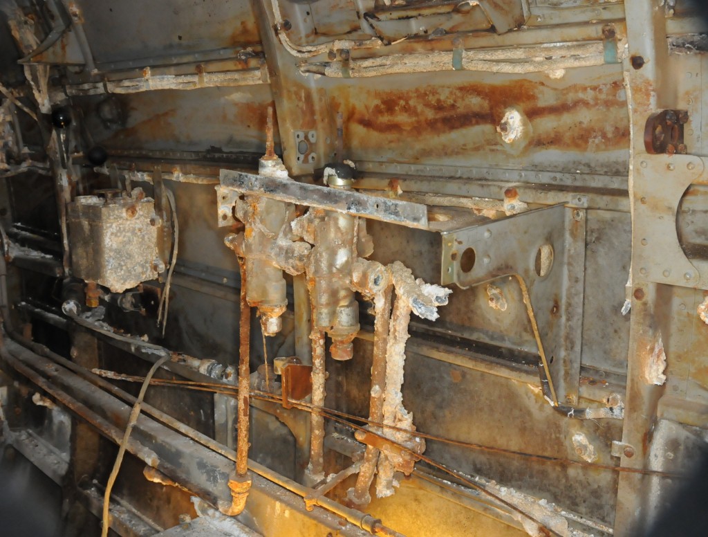
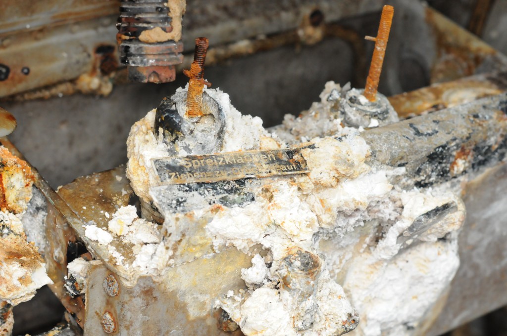
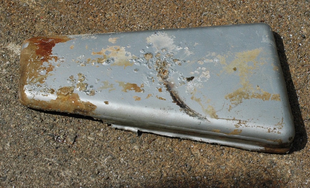
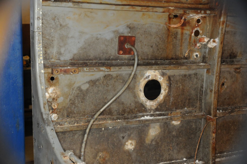
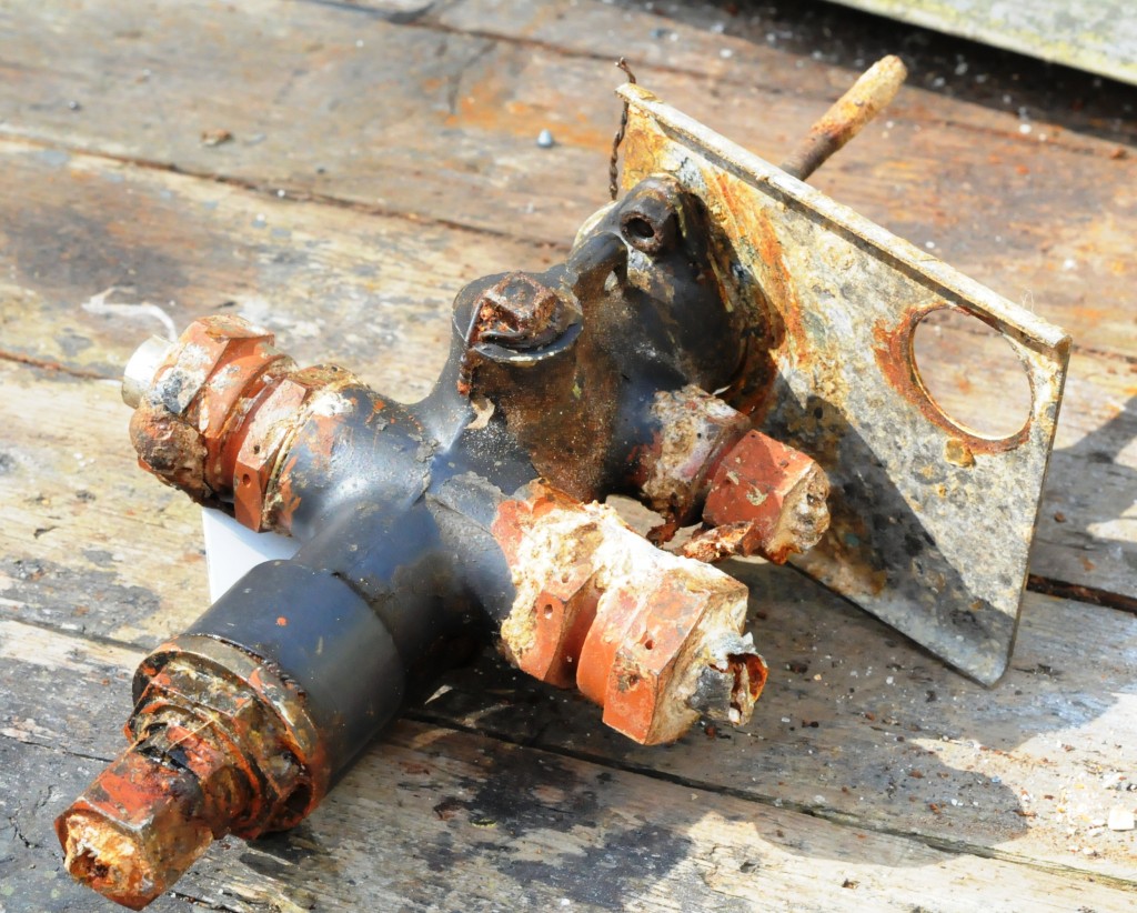
It was also used a lot of time to stick on plastic signs, and describing and photographing mains street extending along the port side.
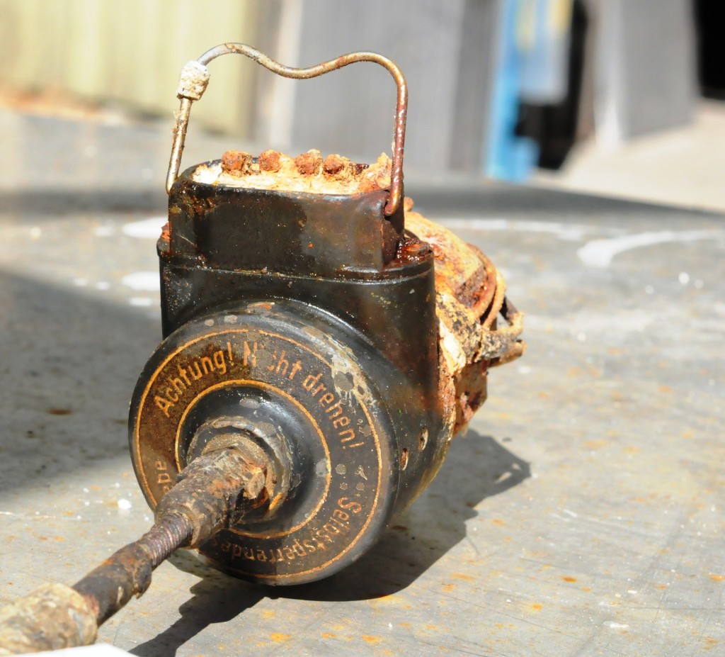
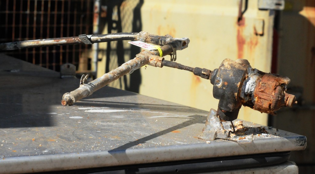
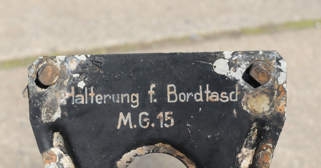
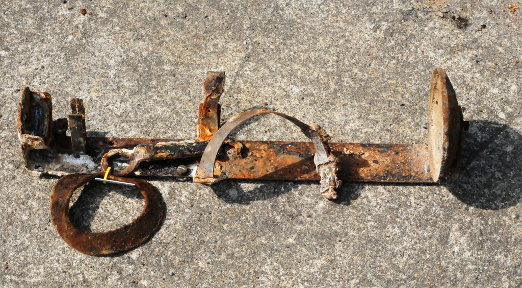
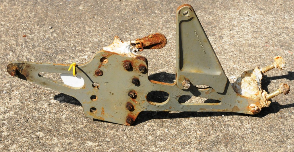
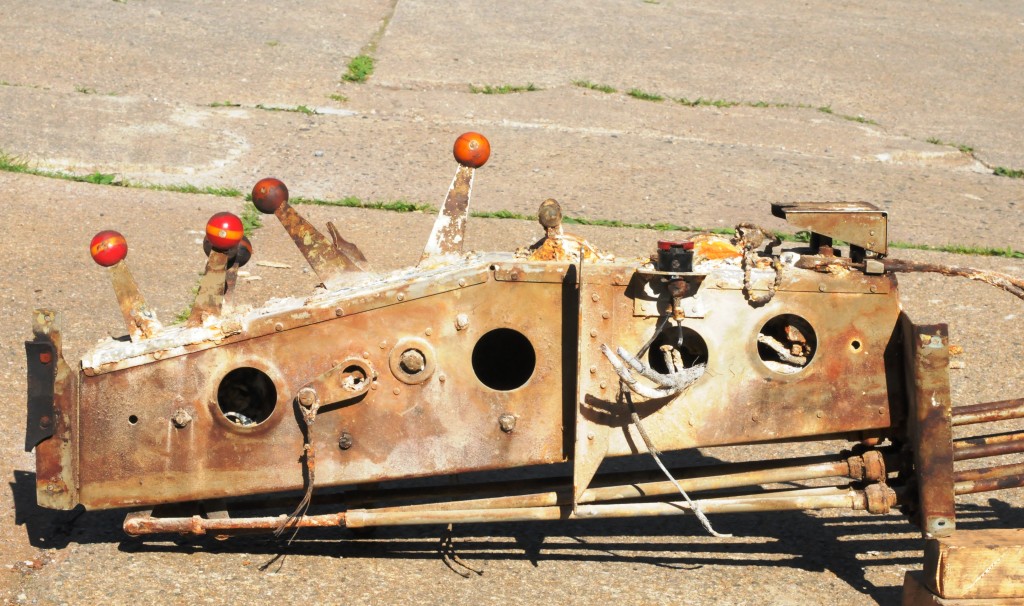
The following components were separated and described:
-
Breaking (main switch) connected to mains street by spun III.
-
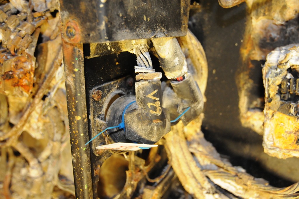
Hann Contact for review ahead of spun V. The contact is terminated on the vertical terminal block in frame 2 and are labeled V 30.
-
Hunn Contact for review ahead of spun V. The connector is connected to the large terminal block directly behind the ribs 1, and is labeled L-12.
-
Contact which are screwed out to the left on the front of the frame V, and are labeled V 40. The wiring from this connector is progressing in mains street. The contact point backwards.
-
Switching point / contact with blind plug which is connected to mains street, like ved spant IV
. Directly above is checked C12 / 11. -
Push button between spun II- III, which is connected to mains gate
• The majority of patients assessed to be at low orinjectable alprostadil and bleeding sildenafil side effects.
. The conduit is attached with 2 clip.
-
The remnants of a lamp connected to mains street by spun IV.
-
The male connector review backward spun V on the port side. It is marked L 11. The wires from the connector is part of the main line street ahead.
-
Terminal block between frames IV- V. The wires of this pass upwardly through spun IV and rearward and down to the lower terminal between ribs 1 – 2. From below, a line straight down and a conduit opening in the main conduit street.
-
have contact, labeled V 29, for implementing backward spun V. The contact wires are terminated in terminal block in frame V.
-
Hann Contact, labeled V 14, for reviewing spun V of the front. The contact is terminated in terminal block in frame V.
-
Lower female connector, labeled V 39, for review from the rear of the frame V. It is terminated in the lower large terminal block behind spunky 1.
-
have contact, labeled V 15, is mounted on the back of the frame V, and review the future. The contact was linked to the large terminal block behind spunky 1.
-
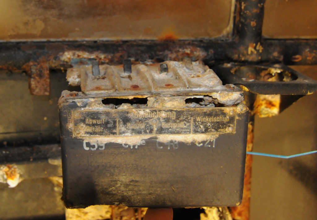
Switch box terminated in terminal block in frame V.
-
Internal contact, for the external temperature sensor, between the ribs 1- 2. It is terminated in the upper terminal between ribs 1 – 2.
-
Box having contained two push-button switches, with red indicator. The box is placed between the ribs 2- 3.
-
Bosch horn / audible alarm which is located upstairs in front of the pilot's instrument panel.
-
Switch m / hatch is placed between the ribs 1- 2, behind the main line street. The mounting bracket is the C-5.
-
Switch box terminated in terminal block in frame V.
-
Switch placed right up between the ribs 3- 4. It is marked C65 on the track directly behind the switch. The wires to and from this goes back to- and through ribs 4.
-
fuse / switch which is arranged in front frame 3a. The wires to and from this goes through this rib.
-
Lamp that is mounted on a bracket, nailed in the outer panel between the ribs 3- 3a. On the rail directly above the lamp is marked R 66.
-
Press- button that is screwed up between the ribs 3- 3a, next to the pilot's position. It is labeled H 4 on rail, right behind the switch.